|
What is an oscilloscope?
An oscilloscope is a measuring instrument
for electronics. Represents a plot of amplitude on the vertical axis and time
on the horizontal axis. It is widely used by students, designers, engineers in
the field of electronics. It is often complemented with a multi-meter, a power
supply and a function generator or arbitrary. Lately, with the explosion of
devices with radio frequency technologies such as WiFi or BlueTooth, the
workbench is complemented by a spectrum analyzer.
The oscilloscope displays the values of
the electrical signals in the form of coordinates on a screen, in which
normally the X (horizontal) axis represents time and the Y axis (vertical)
represents voltage. In analog or digital phosphor oscilloscopes is usually
included other input or control, called "Z-axis" that controls the
brightness of the beam, thus highlighting or off certain segments of the trace
depending on repetition frequency or rate of transition in time.
Down a modern digital oscilloscope shown: 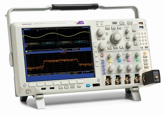
Utilization
On an oscilloscope three types of controls are used as
regulators which adjust the input signal and allow consequently measured on the
screen and thus can see the shape of the signal measured by the oscilloscope
exist basically, this known technical way you can say that the oscilloscope is
used to observe the signal measured.
The first control regulates the X (horizontal) axis and
appreciates fractions of time (seconds, milliseconds, microseconds, etc.,
according to the resolution of the apparatus). The second regulates the Y axis
(vertical) controlling the input voltage (in volts, millivolts, microvolts,
etc., depending on the resolution of the apparatus).
The third is a set trigger (or trigger in English), this
control allows you to synchronize the signals that are repeated so periodically
using a characteristic reference signal, different shot types are used, being
the most common triggering rising or falling edge of the signal, for which the
trigger voltage is defined and whether the edge is rising or falling.
These regulations determine the value of the squaring
dividing the display scale, allowing to know how this represents for each
square, thus knowing the value of the signal to be measured, both in voltage
and frequency or period. 
 Screen of a digital oscilloscope digital representation of an
 unstable signal mode Variable Persistence DPO (digital phosphor)


Analog Oscilloscope
The voltage to be measured is
applied to the plates vertical deflection of a cathode ray tube (using an
amplifier with high input impedance and adjustable gain) while the horizontal
deflection plates a voltage is applied saw-tooth (named because, repeatedly,
grows gently and then falls abruptly). This voltage is produced by a suitable
oscillator circuit and the frequency may be adjusted within a wide range of
values , which can be adapted to the frequency of the signal to be measured.
This is what is called time base.

Figure 1. Schematic representation of an oscilloscope.
In Figure 1 you can see a schematic
representation of an oscilloscope indicating the minimum basic steps. The
operation is as follows:
In the cathode ray tube the
electron beam generated by the cathode and accelerated by the anode reaches the
screen, coated internally with a fluorescent layer that is illuminated by the
impact of the electrons.
If a potential difference to
either of the two pairs of baffles, occurs a deviation of the electron beam due
to the electric field created by the applied voltage is applied. Thus, the
sawtooth voltage, which is applied to the horizontal deflection plates, causes
the beam to move from left to right and during this time, no signal in vertical
deflection plates, draw a line horizontal line on the screen and then back to
the starting point to start a new sweep. This return is not perceived by the
human eye due to the speed at which is done because, in addition, during the
same a shutdown (erase) Partial or beam deflection occurs.
If under these conditions the
signal to be measured (via the adjustable gain amplifier) the beam, also
moving from left to right is applied to the plates vertical deflection, it will
move up or down depending on the polarity of the signal, and with greater or
lesser extent depending on the applied voltage.
Being the coordinate axes divided
by brands, you can establish a relationship between these divisions and
sawtooth period in relation to the X axis and voltage in reference to Y. This
corresponds to each horizontal division one specific time, just as each
vertical division corresponds to a specific voltage. Thus in the case of periodic
signals can be determined both his tenure as its amplitude.
Typical margin scales ranging
from microvolts to a few volts and microseconds to several seconds, makes this
very versatile instrument for the study of a variety of signals. Limitations of analog
oscilloscope
The analog oscilloscope has a number of limitations typical
of operation: - The signals must be periodic . For a stable trace , the
signal must be periodic as it is the frequency of the signal which cools the
trace on the screen.
- Very fast signals reduce glare . As the period of the signal
is observed, the brightness is reduced because the refresh rate decreases.
- Slow signals do not form a trace . Low frequency signals
produce a very slow scan does not allow to integrate the trace retina . This is
solved with high persistence tubes . There were also specially adapted Polaroid
cameras to photograph the oscilloscope screen . Keeping exposure during a photo
of the trace is obtained.
- You can only see if they are repetitive transients.
Digital oscilloscope
Today analog oscilloscopes are
being displaced largely by digital oscilloscopes, among other reasons for the
facility to transfer the measurements to a personal computer or LCD.
In the digital oscilloscope
previously signal is digitized by an analog to digital converter. Relying
reliability display quality of this component, it must be maintained at
maximum.
The features and procedures
outlined for analog oscilloscopes are applicable to digital. However, these
will have additional features such as the shot early (pre-triggering) for
displaying short duration events, or memorizing the oscillogram transferring
data to a PC possibilities. This allows comparing measurements made at the
point of a circuit element. There are also teams that combine analog and
digital stages.
These oscilloscopes added
services and facilities to the user impossible to obtain with analog circuitry,
such as:
- Automatic measurement of peak
signal maximum and minimum values. True RMS.
- Measure signal edges and other
intervals.
- Transient capture.
- Advanced calculations as the FFT
to compute the spectrum of the signal.
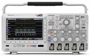
MSO2024 Tektronix Digital
Oscilloscope 200MHz with
4 analog channels and 16 channels digital that can be
used for logical analysis of states and times and analyze
options buses serial
communication as RS232, CAN, LIN,
I2C, Etc.
|
|
|

